Embedded Project
Embedded Traffic Intersection Firmware with State Machine Control and UART Command Interface
In this project, I built a firmware-driven 4-way traffic intersection controller using an Arduino Uno R3. This project explores embedded concepts such as state machines, non-blocking timing, UART communication, cooperative task scheduling, structured protocol design, and direct hardware interaction.
The controller manages North/South and East/West traffic phases, supports both automatic and manual control modes, and exposes a structured UART command interface intended for future Python/Pytest integration testing.
Key Concepts:
- Embedded C++ firmware development
- Finite state machine architecture
- Non-blocking timing
- UART communication
- Structured command protocol
- Cooperative task scheduling
- Firmware observability and debug logging
- Designing firmware for future automated testing
Hardware Layout
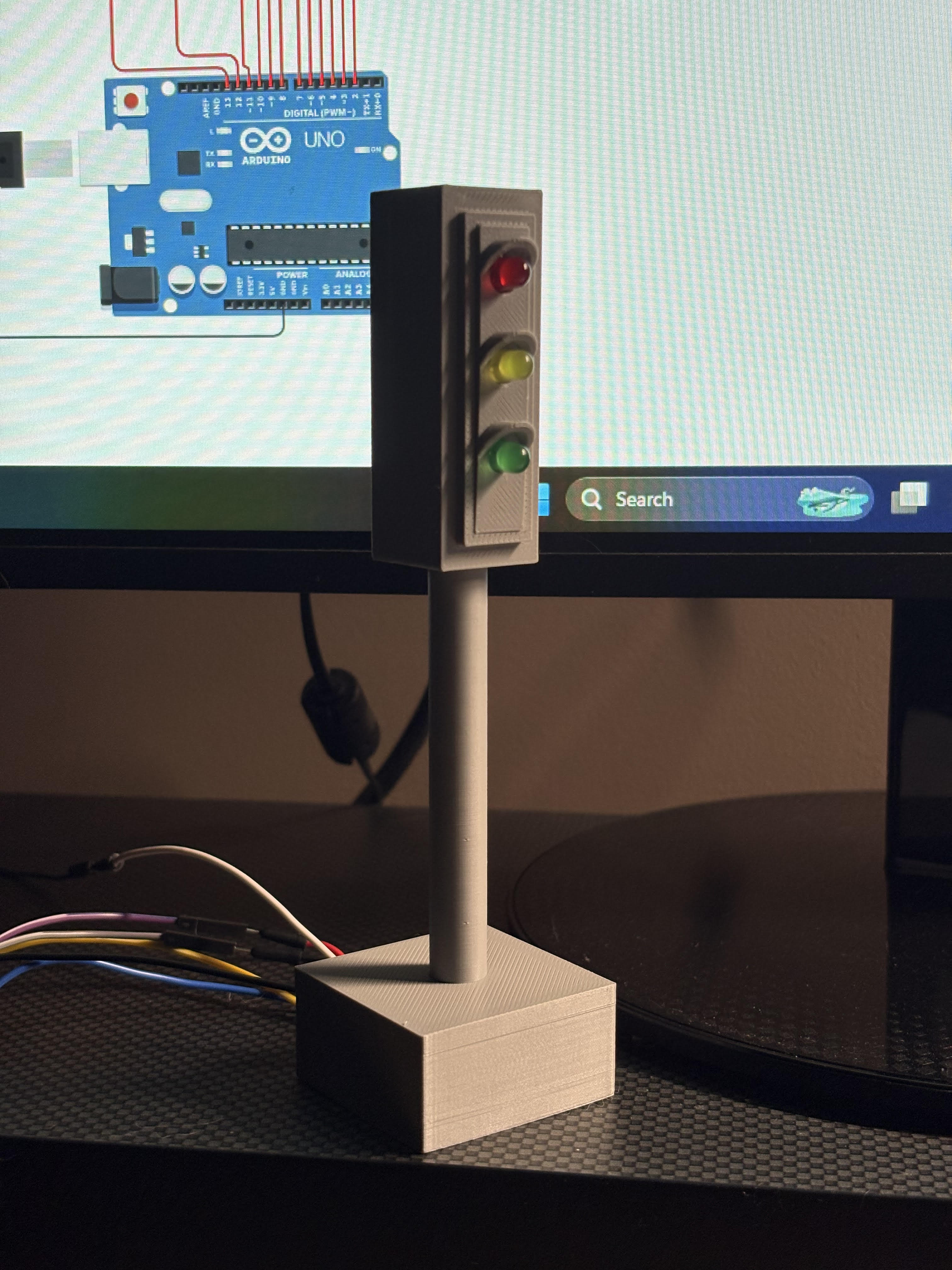
The controller was built with an Arduino Uno R3 and 12 LEDs, representing a 4-way traffic intersection: North, South, East, and West. Each direction consists of independent red, yellow, and green LEDs:
- South:
- Red:
D13 - Yellow:
D12 - Green:
D11 - East:
- Red:
D10 - Yellow:
D9 - Green:
D8 - North:
- Red:
D7 - Yellow:
D6 - Green:
D5 - West:
- Red:
D4 - Yellow:
D3 - Green:
D2
I initially developed the system in Tinkercad, allowing me to plan wiring layouts, test firmware, and safely debug any issues before moving to physical hardware.
Finite State Machine
Instead of procedurally cycling through LEDs inside the main loop, I redesigned the controller as a finite state machine where each traffic phase is represented as a state:
enum TrafficState {
  NS_GREEN_EW_RED,
  NS_YELLOW_EW_RED,
  NS_RED_EW_GREEN,
  NS_RED_EW_YELLOW
};
Computing the next valid state in a set sequence:
TrafficState getNextState(TrafficState state) {
  switch (state) {
    case NS_GREEN_EW_RED:
      return NS_YELLOW_EW_RED;

    case NS_YELLOW_EW_RED:
      return NS_RED_EW_GREEN;

    case NS_RED_EW_GREEN:
      return NS_RED_EW_YELLOW;

    case NS_RED_EW_YELLOW:
      return NS_GREEN_EW_RED;
  }

  return NS_GREEN_EW_RED;
}
I wanted red/green states to last longer than yellow states without hard-coding delays directly into the main loop. Determining transition timing:
const unsigned long GREEN_DURATION = 5000;
const unsigned long YELLOW_DURATION = 2000;

unsigned long getStateDuration(TrafficState state) {
  switch (state) {
    case NS_GREEN_EW_RED:
    case NS_RED_EW_GREEN:
      return GREEN_DURATION;

    case NS_YELLOW_EW_RED:
    case NS_RED_EW_YELLOW:
      return YELLOW_DURATION;
  }

  return GREEN_DURATION;
}
Applying hardware outputs based on state:
void applyState(TrafficState state) {
  allOff();

  switch (state) {
    case NS_GREEN_EW_RED:
      digitalWrite(N_GREEN, HIGH);
      digitalWrite(S_GREEN, HIGH);
      digitalWrite(E_RED, HIGH);
      digitalWrite(W_RED, HIGH);
      break;

    case NS_YELLOW_EW_RED:
      digitalWrite(N_YELLOW, HIGH);
      digitalWrite(S_YELLOW, HIGH);
      digitalWrite(E_RED, HIGH);
      digitalWrite(W_RED, HIGH);
      break;

    case NS_RED_EW_GREEN:
      digitalWrite(N_RED, HIGH);
      digitalWrite(S_RED, HIGH);
      digitalWrite(E_GREEN, HIGH);
      digitalWrite(W_GREEN, HIGH);
      break;

    case NS_RED_EW_YELLOW:
      digitalWrite(N_RED, HIGH);
      digitalWrite(S_RED, HIGH);
      digitalWrite(E_YELLOW, HIGH);
      digitalWrite(W_YELLOW, HIGH);
      break;
  }
}
My controller initially relied on delay() for LED timing. Once UART communication and manual control modes are introduced, these delay() calls will prevent the controller from responding to commands until the delay is completed. So, I replaced blocking delays with non-blocking timing using millis().
Traffic state timing is evaluated continuously, rather than using the blocking delay():
void updateTrafficState() {
  unsigned long currentTime = millis();
  unsigned long stateDuration = getStateDuration(currentState);

  if (currentTime - lastStateChangeTime >= stateDuration) {
    currentState = getNextState(currentState);
    applyState(currentState);
    lastStateChangeTime = currentTime;
  }
}
Separating transition logic, timing behavior, and output control makes the firmware significantly more organized and easier to reason about and expand on.
Observability and Serial Debugging
Now, I could add serial observability through UART logging. The controller outputs to the Serial monitor:
- active traffic state
- timing information
- system responses
- mode changes
Serial.print("TIME: ");
Serial.print(millis());
Serial.println(" | STATE: NS_GREEN_EW_RED");
Rather than relying on looking at all 12 LEDs, the controller could now report its state directly.
UART Command Interface
I added a UART command interface over Serial communication and implemented:
- automatic/manual mode selection
- explicit state control
- status queries
Example commands:
GET STATUS
SET MODE AUTO
SET MODE MANUAL
NEXT
Command handling is processed continuously alongside traffic timing:
void loop() {
  handleSerialCommands();

  if (currentMode == AUTO_MODE) {
    updateTrafficState();
  }
}
Transition Safety Logic
During development, I realized that yellow states would have to be handled differently than green/red states. If I manually switched to a yellow state or switched to manual mode during a yellow state, it would stay yellow, which is awkward and not realistically reasonable.
To resolve this, I separated the states: green/red as stable states and yellow states as timed transitions.
bool isYellowState(TrafficState state) {
  return (state == NS_YELLOW_EW_RED ||
          state == NS_RED_EW_YELLOW);
}

bool isStableState(TrafficState state) {
  return (state == NS_GREEN_EW_RED ||
          state == NS_RED_EW_GREEN);
}
Now, yellow states finish before advancing to the next state and pausing.
if (manualModePending && isStableState(currentState)) {
  currentMode = MANUAL_MODE;
  manualModePending = false;
  Serial.println("OK: mode set to MANUAL after yellow transition completed");
}
Direct State Commands
After adding manual mode, I added direct state commands so the controller could be placed into states as such:
SET STATE NS_GREEN_EW_RED
SET STATE NS_RED_EW_GREEN
This makes the controller deterministic and easier to test because users or systems can place the firmware into known conditions before validating behavior.
The command is only accepted in manual mode so that commands do not override the automatic traffic cycle.
void handleSerialCommands() {
…
else if (command.startsWith("SET STATE ")) {
      if (currentMode != MANUAL_MODE) {
        Serial.println("ERROR: SET STATE only allowed in MANUAL mode");
      } else {
        String stateText = command.substring(10);
        stateText.trim();

        TrafficState requestedState;
        if (parseState(stateText, requestedState)) {
          currentState = requestedState;
          applyState(currentState);

          if (isYellowState(currentState)) {
            lastStateChangeTime = millis();
            currentMode = AUTO_MODE;
            manualModePending = true;
            Serial.println("OK: yellow state entered; controller will return to MANUAL after yellow completes");
          } else {
            Serial.print("OK: state set to ");
            Serial.println(stateToString(currentState));
          }
        } else {
          Serial.println("ERROR: invalid state");
        }
      }
    }
    else {
      Serial.println("ERROR: unknown command");
    }
  }
}
As more UART commands were added, multiple code paths could trigger state changes, so to avoid duplicating logic between automatic transitions and UART-driven transitions, I centralized transition side effects into a dedicated helper.
void requestStateChange(TrafficState newState) {
  currentState = newState;
  applyState(currentState);

  if (isYellowState(currentState)) {
    lastStateChangeTime = millis();
    currentMode = AUTO_MODE;
    manualModePending = true;
    Serial.println("OK: yellow state entered; controller will return to MANUAL after yellow completes");
  } else {
    Serial.print("OK: state set to ");
    Serial.println(stateToString(currentState));
  }
}
Structured Firmware Protocol
I later redesigned the UART interface to use a structured command protocol rather than plain-text commands.
Commands now follow a consistent format: CMD:<COMMAND>;ARG:<VALUE>, such as:
CMD:GET_STATUS
CMD:SET_MODE;ARG:MANUAL
CMD:SET_STATE;ARG:NS_RED_EW_GREEN
CMD:NEXT
void processStructuredCommand(String command) {
…
 else if (command.startsWith("CMD:SET_STATE;ARG:")) {
    if (currentMode != MANUAL_MODE) {
      Serial.println("ERROR: SET_STATE only allowed in MANUAL mode");
      return;
    }

    String stateText = command.substring(18);
    stateText.trim();

    TrafficState requestedState;
    if (parseState(stateText, requestedState)) {
      requestStateChange(requestedState);
    } else {
      Serial.println("ERROR: invalid state");
    }
  }
  else {
    Serial.println("ERROR: unknown structured command");
  }
}
Cooperative Task Scheduling
Although the controller does not run a true RTOS, I wanted to structure the firmware around RTOS-style cooperative task scheduling concepts.
The main loop separates responsibilities into two independent tasks:
void loop() {
  taskHandleCommands();
  taskUpdateController();
}
Each task executes quickly and returns immediately, allowing the firmware to continuously service multiple responsibilities. This allows command handling, timing evaluation, and state management to execute without blocking each other.
Direct Register Manipulation
The South light outputs were wired on pins D11-13, allowing them to be controlled directly through PORTB.
void setSouthLightsDirect(bool redOn, bool yellowOn, bool greenOn) {
  if (redOn) {
    PORTB |= (1 << PB5);
  } else {
    PORTB &= ~(1 << PB5);
  }

  if (yellowOn) {
    PORTB |= (1 << PB4);
  } else {
    PORTB &= ~(1 << PB4);
  }

  if (greenOn) {
    PORTB |= (1 << PB3);
  } else {
    PORTB &= ~(1 << PB3);
  }
}
While only this portion of the controller currently uses direct register access, this was one of my favorite parts of the project because I’m particularly interested in assembly, low-level, and hardware-oriented programming.
Future Physical Hardware and Python Automated Testing
I intentionally designed the UART command interface to support future Python integration testing using pyserial and pytest.
Future tests include:
- validating state transitions
- verifying manual/automatic mode behavior
- testing yellow transition timing rules
- confirming protocol responses
- rejecting malformed commands
This testing will allow the firmware to be validated automatically rather than relying on manual commands.